Description
Allison 5000, 6000 Series Transmission Service Manual Download
This is a complete service repair manual for Allison 5000, 6000 Series Transmission. Using this repair manual is an inexpensive way to keep your vehicle working properly. The manual has detailed illustrations, diagrams, wiring schematics and specifications as well as step-by-step instructions.
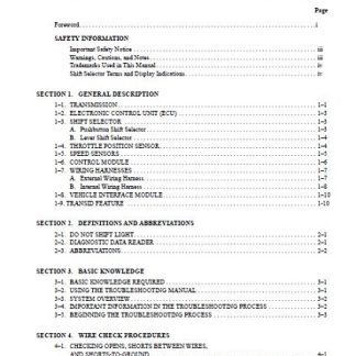
CONTENTS:
GENERAL INFORMATION
1- 1. SCOPE
a. Coverage
b. lllustrations
c . Maintenance Information
1-2. SUPPLEMENTARY INFORMATION
1-3. ORDERING PARTS
1-4. DESIGN FEATURES
a . Transmission-to-Engine Coupling
b. Torque Converter
c. Planetary Gearing
d. Clutches
e. Hydraulic System
f. Power Takeoff
g. Lockup Clutch
1-5. SHIFT CONTROL SYSTEMS
a. Manual-Electric Shift
b . Automatic-Electric Shift
c. Electronic-Control Shift (CEC 1)
d. Electronic-Control Shift (CEC 2)
e . Manual-Hydraulic Shift
1–6. OPTIONS
a. Hydraulic Retarder.
b. Parking Brake
c. Transfer Gears (Dropbox)
d . Output Disconnects
e. Flanges
f. Speedometer Drive
1-7. OPERATING INSTRUCTIONS
a. Operator’s Manual
b. Manual Mode (CEC 1)
c. Manual Mode (CEC 2)
d . Cold Weather Starts (CEC I)
e . Cold Weather Starts (CEC 2)
f . Towing
1-8. SPECIFICATIONS AND DATA
Section 2. DESCRIPTION AND OPERATION
2-1. SCOPE
a. Two Configurations
b. Control Systems
2-2. MOUNTING, INPUT DRIVES
a . Remote Mounting
b. DirectMounting
2-3. LOCKUP CLUTCH
2-4. TORQUE CONVERTER – FIXED
CAPACITY
2-5. TORQUE CONVERTER -VARIABLE CAPACITY
2-6. HYDRAULIC RETARDER
2-7. POWER TAKEOFF (PTO)DRIVES
2-8. SPLITTER CLUTCHES, GEARING
2-9. HIGH-RANGE CLUTCH (FIFTH AND SIXTH RANGE)
2-10. INTERMEDIATE-RANGE CLUTCH, PLANETARY (THIRD AND FOURTH RANGE)
2-11. LOW-RANGE CLUTCH, PLANETARY (FIRST AND SECOND RANGE)
2-12. REVERSE CLUTCH, PLANETARY
2-13. SPEEDOMETER DRIVE
2-14. PARKING BRAKE
2-15.P~,ST~R
2-16. INPUT PRESSURE AND SCAVENGE PUMP
2-17. HOUSING, COVERS
a. Front Cover (Remote Mount Models)
b. Torque Converter Housing
c. Main Housing
2-18. HYDRAULIC SYSTEM
a. System Functions .
b. System Schematics
c. Filter, Main-Pressure Regulator Valve
d. Lockup Clutch Shift Valve
e. Flow (Lockup Cutoff) Valve (Models With Non-Electric Lockup)
f. Check Valve (Models With Non-Electric Lockup)
g. Hydraulic Retarder Valve (Models With Retarder)
h. Converter Pressure Relief Valve (All Models)
1. Converter Pressure Regulator Valve (Models With Retarder)
j. Lubrication Pressure Regulator Valve (Models Without Retarder)
k. Converter-In Check Valve (Models With Retarder) ………… 2-11
2-19. MANUAL-HYDRAULIC CONTROL SYSTEM
a. Manual Selector Valve
b. Neutral Trimmer Valve
c. Intermediate-Range Trimmer Valve
2-20. MANUAL-HYDRAULIC CONTROL SYSTEM CIRCUITS
a. Neutral
b. First Range
c. Second Range
d. Third Range
e. Fourth Range
f. Fifth Range
g. Sixth Range
h. Reverse
2-21. MANUAL-ELECTRIC CONTROL HYDRAULIC SYSTEM
a. Reverse Shift Valve
b. Low-Range Shift Valve
c. Intermediate-Range Shift Valve
d. High-Range Shift Valve
e. Solenoid Pressure Regulator Valve
f. Priority Valve
g. Splitter Shift Valve
h. Protection in the Event of Electrical Interruption
i. Trimmer System
j. Reverse Trimmer
k. Low-Range Trimmer
I. Intermediate-Range Trimmer
m. Splitter-Low Trimmer .
n. Exhaust Regulator Valve
o. Solenoids
p. Shift Selector Assembly
q. Wiring Harness
2-22. MANUAL-ELECTRIC CONTROL HYDRAULIC SYSTEM CIRCUITS
a. Neutral
b. Protection in the Event of Electrical Interruption While Operating in Neutral
c. Protection in the Event of Electrical Interruption While Operating in Forward Ranges
d. First-Range Operation
e. Second-Range Operation
f. Third-Range Operation
g. Fourth-Range Operation
h. Fifth-Range Operation
i. Sixth-Range Operation
j. Reverse Operation
k. Protection in the Event of Electrical Interruption While Operating in Reverse
1. Protection in the Event of Electrical Interruption While Operating Dual-Electric Equipment.
2-23. SPG-CONTROL AUTOMATIC-ELECTRIC HYDRAULIC SYSTEM AND CIRCUITS
c. Lock-In-Range Downshift Protection
d. Lock-In-Range Reset Procedure
e. Operation After Lock-In-Range Reset
f. Electrical Connections
g. Negative-Ground System
h. Positive-Ground System
1. Fusing and Overload Protection
2-24. CEC 1 ELECTRONIC CONTROL HYDRAULIC SYSTEM AND CIRCUITS (Models Without Trim Boost)
a. Electronic Control Unit (ECU)
b. Shift Selector
c. CHECK TRANS Light
d. Throttle Sensor
e. Output Speed Sensor
f. Wiring Harnesses
g. Lockup (Models With Electric Lockup)
h. Operation of the Electronic Control System
2-25. CEC 1 ELECTRONIC CONTROL HYDRAULIC SYSTEM AND CIRCUITS (Models With Trim Boost)
a. Trimmer System
b. Reverse Trimmer
c. Low-Range Trimmer
d. Intermediate-Range Trimmer
e. Splitter-High Trimmer
f. Splitter-Low Trimmer
g. Trim Boost Valve
2-26. CEC 2 ELECTRONIC CONTROL HYDRAULIC SYSTEM AND CIRCUITS (Models With Trim Boost)
a. Electronic Control Unit (ECU)
b. Shift Selector
c. CHECK TRANS Light
d. Throttle Position Sensor
e. Speed Sensors
f. External Wiring Harnesses
2-27. TORQUE PATHS THROUGH THE TRANSMISSION
a. Torque Converter Operation ……… 2-39
b. Lockup Operation …………….. 2-39
c. Neutral Torque Path ….. . ………. 2-40
d. First-Range Torque Path ………… 2-41
e. Second-Range Torque Path ………. 2-42
f. Third-Range Torque Path ……….. 2-43
g. Fourth-Range Torque Path ……….. . 2-44
h. Fifth-Range Torque Path ………… 2-45
1. Sixth-Range Torque Path ………… 2-46
J. Reverse or Reverse-I Torque Path …. 2-4 7
k. Reverse-2 Torque Path ………….. 2-48
Sectioll3. PREVENTIVE MAINTENANCE
3-1. SCOPE ………………………… 3-1
3-2. GENERAL INSPECTION AND CARE . .. 3-1
3-3. IMPORTANCE OF PROPER
TRANSMISSION FLUID LEVEL
a. Effects of Improper Fluid Level . …… 3-1
b. Foaming and Aeration . ………….. 3-1
3-4. TRANSMISSION FLUID LEVEL
CHECK PROCEDURE
a. Cold Check . . . ……….. .. .. . ….. 3-2
b. Hot Check …….. . …………… 3-2
3-5. KEEPING TRANSMISSION
FLUID CLEAN ………………….. 3-3
3-6. TRANSMISSION FLUID
RECOMMENDATIONS
a. Recommended Automatic
Transmission Fluid ………. . ……. 3-4
b. Recommended Viscosity Grade ……. 3-4
3- 7. TRANSMISSION FLUID CHANGE AND
FILTER CHANGE INTERVALS . . ……. 3-4
a. Transmission Fluid Change Interval …. 3-4
b. Filter Element Change Intervals
and Service . . ….. . ….. . ………. 3-5
3-8. FLUID CONTAMINATION
a. Examination at Fluid Change ….. . . . . 3-6
b. Metal Particles . . . . . . . . . . . . . . . . ….. 3-6
c. Coolant Leakage . .. . …… . …….. 3-6
d. Cooler Circuit Filter. …… . … . ….. 3-8
3-9. TRANSMISSION FLUID AND FILTER
CHANGE PROCEDURES …………. . 3-8
3-10. BREATHER …………. . ……….. 3-8
3-11. CHECKING FLUID TEMPERATURE,
PRESSURES
Page
a. Fluid Temperature Gauge ………… 3-9
b. Checking, Adjusting Main Pressure … 3-10
c. Checking Lubrication Pressure ……. 3-11
d. Adjusting Lubrication Pressure
(Models Without Retarder) ………. 3-11
e. Checking Converter-out Pressure ….. 3-11
f. Checking Fluid Velocity Governor
(Pitot) Pressure (Models With Non-
Electric Lockup) ……………… 3-11
g. Checking Stator Control Pressure
(Models With Variable-Capacity
Torque Converter) …………….. 3-11
h. Checking Range and Splitter Clutch
Pressures …….. . …………… 3-12
3-12. LINKAGE
a. Manual Selector Valve Linkage
(Manual-Hydraulic Models) ……… 3-12
b. Retarder Valve Linkage … . .. . ….. 3- 12
c. Output Disconnect Linkage . . … . …. 3-12
3-13. EXTERNAL HYDRAULIC LINES
AND COOLER
a. External Lines ………… . ……. 3-13
b. Cooler ……………… . . . ….. 3-13
3-14. ADJUSTING LOCKUP SPEED (Models With
Non-Electric Lockup)
a. Lockup Speed (in the Equipment) …. 3-13
b. Lockup Speed and Shift Points
(Using a Test Stand) … . …… . …. 3-13
c. Lockup Speed Adjustment ………. 3-13
3-15. ADJUSTING PARKING BRAKE
a. Description …………………. 3-13
b. Procedures ………………….. 3- 13
c. Burnishing New Brakes … . … . …. 3-14
3-16. TRANSMISSION STALL TEST AND
NEUTRAL COOL-DOWN CHECK
a. Purpose ……………………. 3- 14
b. Stall Test Preparation … . ………. 3- 14
c. Stall Test Procedures – Equipment
Without Smoke-Controlled Engines .. . 3-15
d. Stall Test Procedures – Equipment
With Smoke-Controlled Engines ….. 3-15
e. Neutral Cool-Down Check
Procedure ………………….. 3-15
f. Results . . . . . . . . . . . . …. . .. . …… 3-16
Paragraph Page
3-17. PRESERVATION AND STORAGE
a. Storage, New Transmissions
(Prior to Installation) ………… . .. 3-16
b. Preservation Methods ………….. 3-16
c. Storage, One Year- Without
Transmission Fluid ……………. 3-16
d. Storage, One Year- With Transmission
Fluid (Normally Installed in the
Equipment) …………………. 3-16
e. Restoring Transmission to Service …. 3-17
3-18. LUBRICATION OF SHIFT SELECTORSPG-
CONTROL AUTOMATIC-ELECTRIC
MODELS
a. Lubrication Intervals …………… 3-17
b. Clean Before Lubricating ……….. 3-17
c. Lubrication Points . . . . . . . . . . ……. 3-17
3-19. TROUBLESHOOTING THE CONTROL
SYSTEM …………………….. 3-18
3-20. CHECKING, ADJUSTING MANUALELECTRIC
CONTROL SYSTEM
a. Field Test Kit. . …………. . . . .. . 3-18
b. Checking Wiring Harness …….. . .. 3-18
c. Checking Main Control Valve Body .. 3-19
d. Checking Hydraulic Circuits ……… 3-19
3-21. CHECKING, ADJUSTING SPG-CONTROL
AUTOMATIC-ELECTRIC SYSTEM
a. Field Test Kit ……….. . ……… 3-20
b. Checking Wiring Harnesses ……… 3-20
c. Checking Throttle Potentiometer .. . .. 3-22
d. Checking Magnetic Pickup
(Speed Sensor) ……………….. 3- 23
e. Checking Shift Pattern
Generator (SPG) .. ….. .. ….. . … 3-23
f. Checking 24V Overload Protector …. 3-23
g. Checking 12V-to-24V Converter ….. 3-23
h. Checking Control Valve Assembly …. 3-23
i. Checking Hydraulic Circuit …… . .. 3- 23
3-22. TESTING SHIFT SELECTOR ASSEMBLY
a. Manual-Electric Test Equipment … . . 3-23
b. Shop-Constructed Test Lamp Bank … 3-23
c. Testing Manual-Electric
Shift Selector ………………… 3-24
d. Testing SPG-Control Automatic-
Electric Shift Selector … . ….. . .. . . 3-26
3-23. TROUBLESHOOTING THE TRANSMISSION
a. Before Removal or Operation …….. 3-28
b. During Operation ……………… 3-28
c. After Removal From Equipment …… 3-28
d. Troubleshooting Table ………….. 3-28
e. Electronic Controls Troubleshooting … 3-28
Section 4. GENERAL OVERHAUL
INFORMATION
4-l. SCOPE ……………. .- ………… 4-1
4-2. PROCEDURESSUBffiCT
TO CHANGE …………………… 4-1 .
4-3. WELDING PROCEDURES FOR
ELECTRONIC CONTROL
EQUIPMENT …………………… 4-1
4-4. REMOVAL, INSTALLATION OF
TRANSMISSION ………………… 4-1
4-5. REMOVAL OF WIRING HARNESSES
(Manual-Electric and SPG-Control Models)
a. Manual-Electric Shift Model. … . ….. 4-1
b. SPG-Control Automatic-Electric
Shift Model ………… . ………. 4-2
4-6. REMOVAL OF REMOTE COMPONENTS
(Manual-Electric and SPG-Control Models)
a. Shift Selector Assembly ………….. 4-4
b. Shift Pattern Generator (SPG),
12V-to-24V Converter, 24V Overload
Protector, Throttle Potentiometer ….. 4-5
4-7. INSTALLATION OF EXTERIOR
COMPONENTS (Manual-Electric and
SPG-Control Models) . . ….. . ………. 4-5
4-8. TOOLS,EQUIPMENT
a. Special Tools …………………. 4-5
b. Improvised Tools and Equipment …… 4-6
c. Mechanic’s Tools, Shop Equipment … 4-6
4-9. REPLACEMENTPARTS
a. Ordering Infonnation …. . ……….. 4-7
b. Parts Nonnally Replaced …………. 4-7
c. Parts Replacement ……………… 4-7
4-10. CAREFUL HANDLING … . ………… 4-8
Paragraph Page
4-11. CLEANING, INSPECTION
a. Dirt-Free Assembly …………….. 4-8
b. Cleaning Parts ………………… 4-9
c. Cleaning Bearings …………….. 4-10
d. Inspecting Bearings ……………. 4-10
e. Keeping Bearings Clean ………… 4-10
f. Inspecting Cast Parts, Machined
Surfaces ……………………. 4-10
g. Inspecting Bushings, Thrust Washers .. 4-11
h. Inspecting Seals, Gaskets ………… 4-11
1. Inspecting Seal Contact Surfaces …… 4-11
j. Inspecting Gears …. . ………….. 4-11
k. Inspecting Splined Parts ………. . .. 4-11
1. Inspecting Threaded Parts ……….. 4-11
m. Inspecting Retaining Rings ………. 4-11
n. Inspecting Springs …………….. 4-11
o. Inspecting Clutch Plates …………. 4-11
p. Inspecting Swaged, Interference-
Fit Parts ……………………. 4-12
q. Inspecting Balls in Clutch Pistons ….. 4-12
r. Inspecting Pump Gears … . ……… 4-12
4-12. ASSEMBLY PROCEDURES
a. Clutches, Pistons ……………… 4-12
b. Parts Lubrication . …………….. 4-12
c. External Plugs, Hydraulic Fittings ….. 4-12
d. Oil-Soluble Grease …………….. 4-14
e. Sealing Compounds …………. . . . 4-14
f. Lip-Type Seals (Metal-Encased) …… 4-14
g. Interference-Fit Parts . … . ………. 4-15
h. Sleeve-Type Bearings ………….. 4-15
1. Bearings (Ball or Roller) ………… 4-15
4-13. REMOVING (OR INSTALLING)
TRANSMISSION
a. Drain Transmission Fluid ……….. 4-15
b. Check Linkages and Lines ……….. 4-15
c. Remove, Clean Transmission …….. 4-15
d. Install Transmission ……………. 4-15
4-14. WEAR LIMITS …….. .. … . …….. 4-16
4-15. SPRING SPECIFICATIONS ……….. 4-16
4-16. TIGHT-FIT FLANGES
a. Removal of Flanges ……………. 4-16
b. Installation of Flanges … . …… . … 4-17
4-17. TEFLON® LIP-TYPE SEALRINGS
a. Removal .. .. . . .. . ……… .. . .. . . 4-17
b. Installation ……………….. . .. 4-18
4-18. DETERMINING PrO BACKLASH LIMITS
a. Determining Backlash Between
Drive and Driven Gear (Quantity A) .. 4-18
b. Determining Backlash Between
Drive and Driven Gear (Quantity B) .. . 4-18
c. Determining the Total Backlash
in the Gear Train (Quantity C) ……. 4-18
4-19. TORQUE SPECIFICATIONS …… . … 4-19
Sectiorl5. DISASSEMBLY OF
TRANSMISSION
5-1. SCOPE … …………………….. 5-1
. 5-2. GENERAL INFORMATION FOR
DISASSEMBLY OF TRANSMISSION
a. Preparation for Disassembly ………. 5-1
b. Removal of Control Components … … 5-l
c. Disassembly Information ….. . …… 5-1
d. Lifting, Handling ………………. 5-1
5-3. TRANSMISSION DISASSEMBLY
a. Removal of Exterior Components …… 5-1
b. Removal of Torque Converter and
Related Components ……………. 5-9
c. Removing Torque Converter
Elements … . ……………….. 5-11
d. Removal of Torque Converter
Housing, Retarder Housing, and
Related Components . …… . .. ….. 5-13
e. Removal of Pump, PTO, and
Idler Gears … . ………………. 5-12
f. Separating Converter Housing and
Retarder Housing, and Removing
Related Parts .. …………. . ….. 5-14
g. Disassembly of Retarder Housing,
Turbine Shaft, and Related Parts
(Models With Retarder) ……. ….. 5-16
h. Disassembly of Converter Housing,
Turbine Shaft, and Related Parts
(Models Without Retarder) ….. . …. 5-17
i. Removal of Transmission Output
Components . . ……………….. 5-18
j. Removal of Range Planetaries,
Clutches, and Related Parts From
Output End of Transmission
Main Housing …………. . …… 5-22
k. Removal of Splitter Clutch and
Related Parts . … …………….. 5-26
Paragraph Page
Section 6. REBUILD OF SUBASSEMBLIES
6–l. SCOPE …. …… …………. ….. . 6-1
6–2. GENERAL~ORMATIONFOR
REBUU…D OF SUBASSEMBLIES ……. 6-1
6–3. MANUAL-ELECTRIC CONTROL
SHIFT SELECTOR
a. Disassembly . .. ……… … . …. … 6–1
b. Assembly …. . ………….. . . …. 6–4
6-4. SHIFT PATTERN GENERATOR
(SPG), 24V OVERLOAD PROTECTOR,
l2V-to-24V CONVERTER ….. …. …. 6–7
6-5. SPG-CONTROL SIDFT SELECTOR
a. Disassembly …………………. . 6–8
b. Assembly …. . ……………….. 6–8
6–6. SPG-CONTROL THROTTLE
POTENTIOMETER
a. Disassembly .. . .. ……………. 6-11
b. Assembly …………………… 6-11
6–7. CEC I SHIFT SELECTOR – LEVER
a. Disassembly ……………… . … 6-11
b. Assembly …………………… 6-13
6–8. CEC 1 SHIFT SELECTOR – PUSHBUTTON
a. Disassembly …………………. 6-14
b. Assembly ………………… … 6-17
6–9. ELECTRONIC CONTROL UNIT
(ECU) CEC I PROM REPLACEMENT
a. Removal of PROM ……………. 6-17
b. Installation of PROM ….. . …….. 6-18
6–10. CEC 2 SHIFT SELECTOR- LEVER
a. Disassembly . … …………. . .. . . 6-19
b. Assembly …………………… 6-19
6–11. CEC 2 SHIFT SELECTOR -PUSHBUTTON
a . Disassembly ….. ……. . ….. …. 6-19
b. Assembly .. .. . .. ……….. . … .. 6-21
6–12. PARKING BRAKE ASSEMBLY
a . Disassembly … .. ……………. . 6-21
b. Assembly ……. . …………… . 6-22
6-13 . FILTER ASSEMBLIES
a. Disassembly – Earlier Filters . . . …. 6-22
b. Assembly- Earlier Filters ….. . . … 6-23
c. Disassembly – High-Efficiency
Filters …… . ……………….. 6-23
d. Assembly – High-Efficiency
Filters …………………. . …. 6-23
e. Disassembly – Allison Remote
Filter ………………………. 6-23
f. Assembly – Allison Remote Filter … 6-23
6-14. STATOR CONTROL VALVE BODY
(Models With Variable-Capacity
Torque Converter)
a. Disassembly …………………. 6-23
b. Assembly …………………… 6-24
6-15. MAIN-PRESSURE REGULATOR VALVE
BODY ASSEMBLY
a. Disassembly …………………. 6-24
b. Assembly …………………… 6-24
6-16. NON-ELECTRIC LOCKUP VALVE BODY
ASSEMBLY
a. Disassembly ………………… 6-24
a. Assembly . . . . . . . . . . . . . . . . . . . . . . . 6-25
6-17. ELECTRIC-CONTROL LOCKUP VALVE
BODY ASSEMBLY
a. Disassembly …………………. 6-25
b. Assembly …………………… 6-26
6-18. MAIN-PRESSURE TRANSFER TUBE
ASSEMBLY
a. Disassembly …………. . …….. 6-26
b. Assembly …………………… 6-26
6-19. MANUAL-HYDRAULIC CONTROL
VALVE BODY ASSEMBLY
a. Disassembly …………… . …… 6-27
b. Assembly …………………… 6-27
6-20. ELECTRIC/ELECTRONIC-CONTROL
VALVE BODY ASSEMBLY
(Models Without Trim Boost)
a. Disassembly ….. . ……… . . . …. 6-28
b. Assembly ……. .. … … ……… 6-31
6-21. ELECTRONIC-CONTROL VALVE
BODY ASSEMBLY (Models With Trim Boost)
a. Disassembly ……… . ………… 6-34
b. Assembly ……. . ……… . …. . . 6-35
6-22. STRAINER ASSEMBLY
a. Disassembly ….. . …. . ……….. 6-38
b. Assembly …………………… 6-38
6-23. HYDRAULIC RETARDER CONTROL
VALVE BODY ASSEMBLY
a. Disassembly . ……. . ………… 6-38
b. Assembly ……. . … … ………. 6-38
Paragraph Page
6-24. LOCKUP-CLUTCH PISTON REWORK
a. Inspection …………………… 6-39
b. Repair ……………………… 6-39
6-25. CONVERTERDRIVEHOUSINGASSEMBLY
(Remote-Mount Models)
a. Disassembly ………………… 6-39
b. Inspection and Repair …………. 6-40
c. Assembly …………………… 6-40
6-26. FLYWHEEL ASSEMBLY
(Direct-Mount Models)
a. Disassembly ……….. .. ……… 6-40
b. Inspection and Repair ………….. 6-41
c. Assembly …………………… 6-41
6-27. STATOR ASSEMBLY – FIXED-CAPACITY
TORQUE CONVERTER
a. Disassembly …………………. 6-41
b. Assembly …………………… 6-41
6-28. STATOR ASSEMBLY- VARIABLECAPACITY
TORQUE CONVERTER
a. Disassembly … . ……………… 6-42
b. Assembly …………………… 6-42
6-29. TORQUE CONVERTER PUMP ASSEMBLY
a. Disassembly ………….. .. …… 6-44
b. Assembly …………………… 6-44
6-30. INPUT PRESSURE, SCAVENGE PUMP
ASSEMBLY
a. Disassembly . … …….. .. …….. 6-45
b. Assembly ……………….. . … 6-45
6-31. TORQUE CONVERTER HOUSING
ASSEMBLY
a. Disassembly … ……………… 6-45
b. Assembly …………………… 6-46
6-32. SPLITTER SUN GEAR ASSEMBLY
a. Disassembly ……………… .. .. 6-47
b. Assembly …………………… 6-47
6-33. SPLITTER PLANETARY CARRIER
ASSEMBLY
a. Disassembly …………………. 6-48
b. Assembly ……. .. ….. . ….. . … 6-48
6-34. SPLITTER-LOW CLUTCH AND
DRUM ASSEMBLY (CL(B)T, M 5600, and
S 5600 Models)
a. Disassembly …. … …. . …. . … . 6-50
b. Assembly …………………… 6-5
6-35. SPLITIER-LOW CLUTCH AND DRUM
ASSEMBLY (M 6600, S 6600 Series Models)
a. Disassembly ………………… 6-51
b. Assembly …………………… 6-52
6-36. HYDRAULIC RETARDER HOUSING
ASSEMBLY
a. Disassembly ………………… 6-52
b. Assembly …………………… 6-52
6-37. OUTPUT DRIVE HOUSING ASSEMBLY
a. Disassembly ………………… 6-52
b. Assembly ………………….. 6-52
6-38. OUTPUT DRIVE HOUSING
a. Disassembly ………………… 6-53
b. Assembly …….. . …………… 6-53
6-39. BEARING RETAINER ASSEMBLY
a. Disassembly ……….. . ……… 6-54
b. Assembly …… . …………….. 6-54
6-40. OUTPUT DISCONNECT ASSEMBLY
a. Disassembly ………………… 6-54
b. Assembly …………………… 6-55
6-41. OUTPUTDRIVEGEARASSEMBLY
a. Disassembly .. . . …….. . …….. 6-57
b. Assembly …………………… 6-57
6-42. OUTPUT IDLER GEAR ASSEMBLY
a. Disassembly ……….. . …. . …. 6-57
b. Assembly ……….. . ….. . … . .. 6-57
6-43. TRANSFER GEAR HOUSING
(DROPBOX) ASSEMBLY
a. Disassembly . . ……….. . ……. 6-57
b. Assembly . …. . ……………… 6-58
6-44.REVERSEPLANETARY
CARRIER ASSEMBLY
a. Disassembly . ……….. . …….. 6-59
b. Assembly ….. . ……….. . ….. 6-59
6-45. LOW-RANGE PLANETARY CARRIER
ASSEMBLY
a. Disassembly … . …….. . ……. . 6-61
b. Assembly ………………….. 6-61
6-46. SPLITTER OUTPUT SHAFf AND
COLLECTOR RING ASSEMBLY
a. Disassembly ………………… 6-62
b . Inspection and Repair … . .. . ….. . . 6-62
c. Assembly …….. . …………… 6-63
Paragraph
6-47. INTERMEDIATE-RANGE PLANETARY
CARRIER ASSEMBLY
Page
a. Disassembly …………………. 6-63
b. Assembly …………………… 6-63
6-48. HIGH-RANGE CLUTCH AND
DRUM ASSEMBLY
a. Disassembly …… . …………… 6-65
b. Assembly …………………… 6-65
6-49. TRANSMISSION MAIN HOUSING
ASSEMBLY
a. Disassembly …………………. 6-66
b. Assembly …………………… 6-66
Section 7. ASSEMBLY OF TRANSMISSION
7- 1. SCOPE ….. . .. . ……………….. 7-1
7-2. GENERAL INFORMATION FOR FINAL
ASSEMBLY ……………………. 7-1
7-3. TRANSMISSION ASSEMBLY (All Models)
a. Installing Splitter Ring Gear,
Intermediate-Range Carrier Assembly,
High-Range Clutch, and Intermediate-
Range Clutch …………………. 7- 1
b. Installing Low-Range Ring Gear,
Low-Range Clutch, and Reverse
Clutch Anchor ………………… 7-5
c. Installing Low-Range and Reverse
Planetaries and Reverse Clutch …….. 7-7
d. Installing Output Drive Housing
Components (Straight-Through Models)
e. Installing Transfer Gear Housing Assembly and Rear Cover (Dropbox Models)
f. Installing Splitter Output Shaft
Retaining Ring, Splitter-High Clutch
g. Installing Splitter Planetary, SplitterLow
Clutch, and Hydraulic Retarder (Models With Retarder)
h. Installing Converter Housing Components
i. Installing Torque Converter Housing
(Models With Retarder) . . … . …… 7-21
j. Installing Splitter Planetary, SplitterLow
Clutch, and Converter Housing
(Models Without Retarder) ………. 7-22
k . Installing Torque Converter
Pump, Stators ……………….. . 7-25
1. Installing Torque Converter
Turbine, Lockup Clutch, and
Input Components ……….. … … 7-27
m. Installing Exterior Components
(All Models) ………….. … …. . 7-29
n. Power Takeoff Gear Backlash ….. . .. 7-37
7-4. INSTALLATION OF CONTROL
COMPONENTS ……. … …. . …… 7-37
Section 8. WEAR LIMITS AND SPRING DATA
8-1. WEAR LIMITS DATA
a. Maximum Variations .. ………….. 8-1
b. Cleaning , Inspection ……………. 8-1
8-2. SPRING DATA ……. ……… .. …. . 8-1
Pages: 326
Format: PDF file
File size: 14 mb
Model: Allison 5000, 6000 Series
Compatibility: Windows/Mac/Tablet/Android/Iphone
Notes: Download only
Reviews
There are no reviews yet.